
DIY Rotary Aluminum Can Crusher

I built this rotary can crusher, and you can see a video of it running HERE.
There are several versions of this design floating around the Internet. If you want to build one, here are some dimensions and key design points.
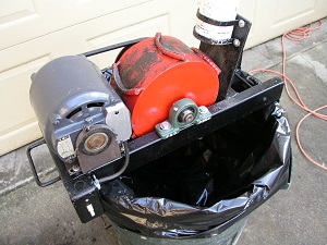
I made the drum from a short piece of pipe and welded the two side plates on. The drum measures 8-1/2″ in diameter and is 4-1/2″ long, and uses a 3/4″ diameter shaft. The entire assembly turns on pillow block bearings.
The drum’s side plates are circles of 1/4″ plate, fitted inside the drum. I welded them in place, and used an angle grinder to grind down the welds and leave nice smooth sides on the drum.
The drum does not spin fast enough for balance to be a problem. What is important is that the shaft it rotates on be dead center to the pipe’s circumference and square to the sides. To avoid an out of round or wobbly drum take your time with the set up of the two parts prior to welding them.
Using a center gage I carefully located and marked the center point of both sides of the drum. Then I drilled holes that were about an 1/8″ larger than the shaft. The large gap between the sides and the shaft allows for adjustment and for weld penetration. I used magnetic welders’ clamps to lightly hold the shaft in place while using a dial indicator to get the shaft exactly in the center and square to the drum’s sides. Once I was happy I had it right I welded the shaft to the side plates.
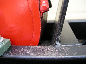
The crush plate that the drum crunches the cans against is 1/4″ thick steel. I welded it at a 15 degree angle off vertical. The relationship between the drum and the plate are critical to the operation. The gap at its narrowest point is 7/8″.
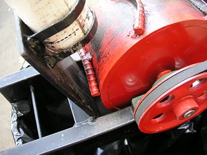
I used an old metal tennis ball can for the feed chute. To mount the chute I made up some U-brackets from flat stock. This allowed me to adjust the chute up and down relative to the crush zone.

The drum has teeth that are made from 1/2″ rebar and welded on. Where the teeth strike the can is very important. The teeth need to strike the can first in the softer sides of the can, and away from the stiff bottom. I ground out one side of the bar to create a sharp edge. Next I bent them into a U-shape with a radius similar to the can. The sharp edge, the radius, and the height all work together to reliably grab the can and pull it through the crush zone.

The motor is 1/3 hp and turns at 1725 RPM. The motor pulley is 1-1/2″ in diameter and it drives a 6″ diameter pulley on the drum. Due to the mass of the drum, it takes a second to for it to get up to speed. Once the drum is rotating that same mass acts like a flywheel and this allows it to swipe a can without slowing down.

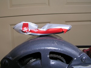
In operation, first the teeth hit the side of the can just above the stiffer bottom and begin to pull it down through the crush zone. As the can is pulled down the bottom is folded up against one side and then the top of the can is folded back over in the other direction.